
Download
Abstract
The late motive of this project is to motorize a rotary injection valve by using a DC-motor (the cheapest option) that has been recovered from obsolete equipment such as a CD reader unit. To prevent the motor being continuously connected and possibly damaged, some electronics must be used to control the direction of rotation, the movement trigger and the duration of action. The operation of this electronic controller is checked when a DC-motor is used to operate a four-way rotary valve, being possible to insert a volume-controlled liquid segment in a current that flows inside a tube without interrupting the flow.
Description
The injection valves used by commercial analytical equipment are manual or motorized by using a stepper motor. These motors are accurate and reliable, but they are relatively expensive and their electronics and programming is complex. A much more economical alternative would be to use a DC-motor that can also be obtained from many scraps of electrical or computer equipment such as, for example, CD or DVD reading units of desktop computers, toys with moving parts or razors with batteries. The problem with using these motors is that they are designed to be in continuous operation and the rotary valves are only activated for very short periods. To adapt the motor operation to how the valve works, it is necessary to design an electronic controller that manages when the motor must be activated, for how long and in which direction it must turn.

The block diagram of the DC motor controller we have designed is shown in the previous figure. It is a controller that, connected to a 12 or 15VDC power supply, can work alone. The action of the motor starts when the push-button is pressed. This button generates a signal that activates a monostable circuit configured to allow the activation of the motor for a certain time, after which the motor stops preventing it from being damaged or overheating. The signal of the push-button also acts on a flip-flop that stores a bit of memory, indicating the turn direction of motor. An H-bridge is responsible for polarizing the motor according to the value of this bit. Each time the button is pressed, the motor is activated in a different direction, which means that the valve state changes.
The controller is designed so that it can be coupled to an Arduino microprocessor. The use of this processor allows that a digital signal simulate the actuation of the pushbutton triggering the change of state of the valve. In this way the valve can be operated from a remote computer, since Arduino can communicate with it through a USB connection. This computer can also read the current state of the valve, so that the synchronization is complete. If an Arduino is connected to the controller, both devices can be powered from the same source, thus saving the use of two different power-source.

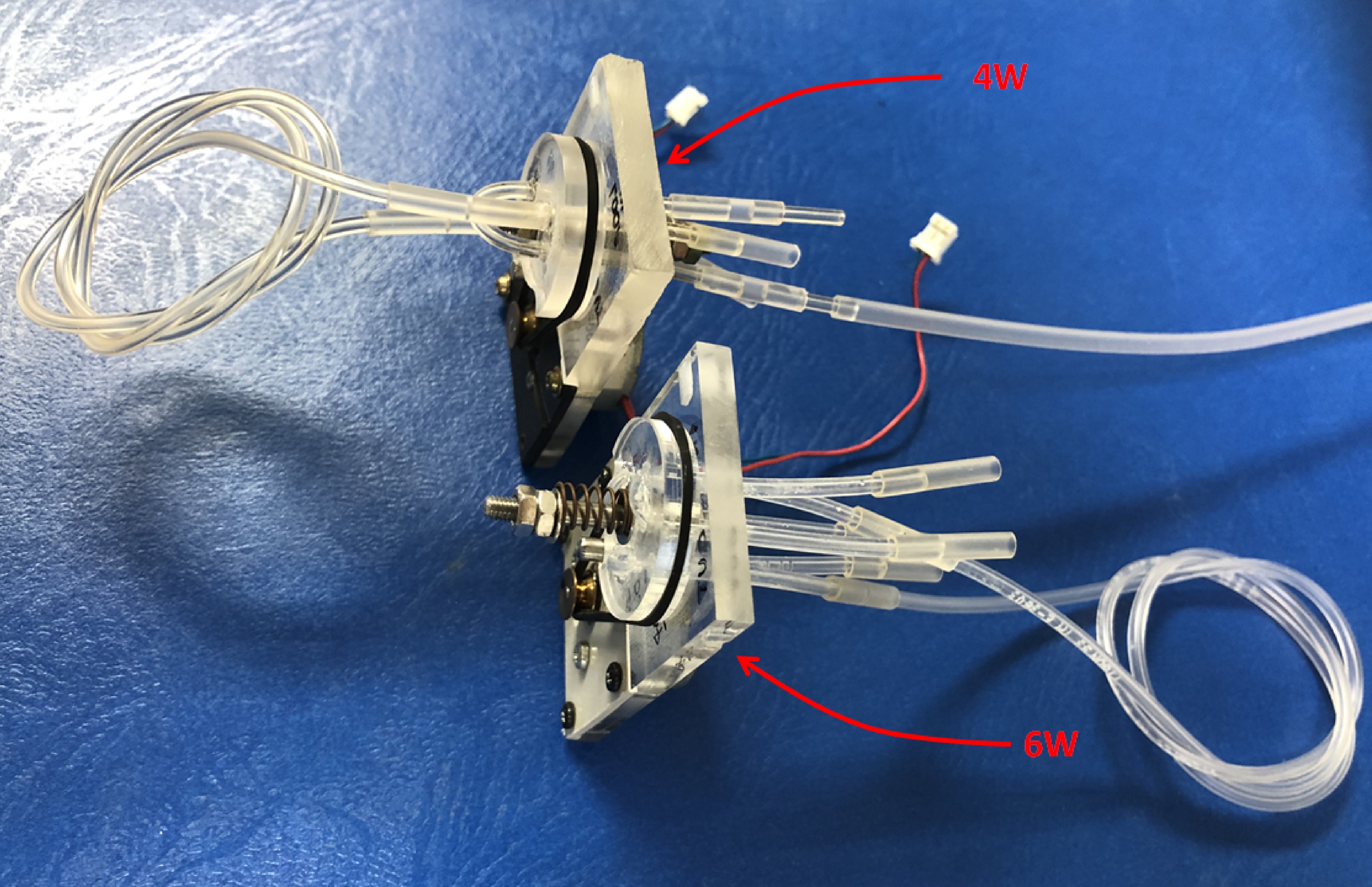
The rotary valves are composed of a fixed part, to which the liquid inlet and outlet pipes are connected, and a mobile part that rotates with respect to an axis, in which the internal connections of the valve are housed. The DC motor is coupled to the valve in such a way that it drives the rotation of the moving part. Our design uses a drive belt between the motor shaft and the rotating part. To avoid liquid leakage, the facing faces of both pieces must be totally coplanar and kept pressed against each other (we use a spring). In addition, the liquid channels must be perfectly aligned in the two positions of the valve, for this a mechanical stop is used and the motor must push the moving part from one stop to the other. By modifing the liquid channel desing, you can change the configuration of valves, making a 4 ways valve, 6 ways valve, etc.
 |
 |
 |
All the parts needed to assemble the valve have been manufactured in methacrylate to show the design with greater clarity. The electronics are separated from the area with the circulating liquids behind a wall to avoid short circuits in case of leaks. Among the published material you can find detailed drawings of all the parts, assembly instructions, electrical diagrams of the controller, tracks and components masks to make the PCB by photoetching, 3D printing files, bill of components and materials and much more.
Demostrative video
The video below shows that the concept of a valve motorized with a DC-motor is fully functional. It is possible to operate a rotary valve with a such motor by only pushing a button.
